Welcome back for part two of the naked Aero Ektar Speed Graphic project. What was once known as the AERO Peacemaker is now called the AEROgraphic (I changed my mind 😉 )
If you’re coming straight from part one and are confident enough to jump right in, please feel free to scroll down a bit past the recap.
If you’re reading this for the first time, I highly recommend you read part one first. If you happen to be looking for the other parts of this series, use the links below to jump to the section you’re looking for:
- The AEROgraphic project part 1 – introduction and required materials
- The AEROgraphic project part 2 – disassembly and strip down (this article)
- The AEROgraphic project part 3 – preparing and finishing the body
- The AEROgraphic project part 4 – reassembly
- The AEROgraphic project part 5 – focal plane shutter and rangefinder tuning
- The AEROgraphic project part 6 – conclusion and example images
As with part one, this is quote a long article and if there’s a specific section you’d like to jump to, please use the table of contents below:
A quick review
In part one of this six part series I gave you a bit of history on the Speed Graphic camera and Aero Ektar lens, suggested what you should buy if you’re planning on starting from scratch, gave you a glimpse at the finished article and discussed my rationale, materials and the tools you will need before you begin this project.
The previously mentioned camera manufacture dates are important for reasons described in part one. In short it means you will have a new-style side-mounted rangefinder. This will allow you to accurately tune the rangefinder to your lens and not solely rely on the ground glass alone for critical focus. This may not be important to you but as this is a street photography project, its is to me.
Here’s the materials and tools list again, split into “required” and “optional” items.
Required materials and tools
- Camera – Graflex Pacemaker Speed Graphic or Crown Graphic – 1947-1954/5.
- Screwdrivers: 1x cross head, 1x slot head, approximately 4mm wide.
- Precision / watchmaker’s screwdriver set.
- Needle nose pliers.
- A small wooden mallet.
- A small coin no more than 2mm thick.
- A small magnet.
- A small ruler, preferably metal.
- 20-30 resealable plastic bags (at least 10x15cm).
- A sharpie or soft pencil.
- A notepad – preferably Shoot Film Co’s Photomemo.
- Some rubber bands.
- A small, sharp craft knife.
- A small metal spoon.
- Strong scissors.
- PVC / wood glue.
- Painter’s tape / masking tape.
- Electrician’s tape, black.
- Sandpaper / sanding blocks (three sheets each of 120, 280, 600 and 1000 grit or similar paper, plus at least one medium and one fine sanding block).
- Some kitchen / cooking foil.
- Wooden chopsticks, 1-2 pairs.
- A lens cloth, small piece of silk or lens cleaning papers.
- Dishwashing soap.
- Paint stripper.
- Matte black spray paint.
- Wood stain (colour of your choice: liquid or staining cloth).
- Clear varnish (spray or liquid).
- A 2-3cm wide paint brush.
- A small sponge.
- A kitchen scouring pad (not metal).
- Protective gloves.
- Several expendable containers for your paint, varnish, paint stripper, etc.
- A UV lamp / flexible LED lamp or a windowsill and direct sunlight
- Patience, patience, patience.
Optional materials, tools and accessories
This materials list, the grips and cable release really are optional but will make the final product much easier to use, as well as adding a final bit of polish.
Here’s the list:
- Linhof (an M4 nut/bolt pair x2), or Graflex left hand grip (with mounts).
- Shutter speed testing tool – photocell, not sound based
- 50cm cable release – Linhof or Hakuba. It must have a “strong” action that cannot be suppressed with a finger over the pin.
- Saddle soap and dubbin.
- Matte black nail varnish.
- External cold shoe mount kit x2.
- 3-axis hot shoe spirit level.
- External hotshoe viewfinder (~180mm).
- Harley Davidson matte black “crinkle” paint.
- One black and one white paint stick.
Before you get your hands dirty: preparation
For this portion of your build you will require two to three hours and the following items to hand:
- Camera – Graflex Speed Graphic Pacemaker or Crown Graphic.
- Screwdrivers: 1x cross head, 1x slot head, approximately 4mm wide.
- Precision / watchmaker’s screwdriver set.
- Needle nose pliers.
- A small wooden mallet.
- A small magnet.
- 20-30 sealable plastic bags (at least 10x10cm).
- A craft knife.
- String
- Wooden chopsticks.
- Patience, patience, patience.
All set? Let’s begin.
Disassembly and bagging parts.
I’m going to do my best to describe the optimal order for removal of parts. Once you’ve popped off a few items, you will likely be tempted to proceed quickly but please try to keep a slow and methodical pace. Removal of certain parts can be fiddly and you’ll need to be confident you can put them back together again. Use the magnet in the materials list to grab and lost screws and please try not to work over deep pile carpet!
When you remove a component or set of components, place it/them into one of your resealable bags and mark the bag with the name of the component(s) as soon as possible. It’ll make life MUCH easier when you get to part four of this guide.
It’s worth stating that there is little skill involved in this aspect of the project. You are simply being methodical about tearing apart your camera. Consumption of alcohol is not advised during this step but it’s not frowned upon either.
Finally, where I discuss components that aren’t included on the Crown Graphic, I will do my best to make a note.
Getting the camera ready
Having a cameraphone to hand helps. Use it to take pictures of the camera before, during and after you start tearing it apart. These pictures will come in handy during reassembly.
Before you begin:
- Make sure you have removed your lens and board from the front standard (the bit where the lens board is mounted).
- Unlock and push the front standard all the way into the body then lock it into place – a small lever at the base of the front standard should be flipped to one side in order to do this.
- Release the camera bed and lock it in the closed position.
- Speed Graphic users should release the rear shutter until the shutter speed indicator reads “O”. This will set the shutter to an open position.
When I mention the left or right of the camera, it’s from the perspective as you look at the camera from the front.
There are 15 steps ahead. If you’re ready, it’s time to start.
Step 1: Removing the Graflock back, mount and bellows
Remove the Graflock back from the camera using the two spring-mounted clips on the top and bottom and put it somewhere safe. There are six screws holding the Graflock mount to the camera. There are two at the top, three at the bottom and one on the right hand side.

Remove them and put them in your first bag. Seal the bag and label it “Graflock mount”. The mount can now be removed and put somewhere safe. You may need to lever the mount free from the body using a precision screw driver. When you are done you can reattach the Graflock back to the mount and set it to one side.
Inside the rear of the camera you will see retaining clips on the top and bottom of the frame (assuming you set your shutter to “O”). Use a flat precision screwdriver to get under one side of each clip and lever it out of place. Place the clips into a bad marked “Bellows mount“.

With the clips free, you must detach the rear part of the bellows, which snap into place on the left and right of the frame. The clips are part of the of rear frame of the bellows and you can use the same screwdriver to free them. See the right of the image below.

When the bellows are free, move to the top of the camera.
Step 2: Optical viewfinder
Remove the optical viewfinder from its mount by pushing down on the small retaining of the left lever and pushing the finder forward. Put it to one side.
")
")
As you can see from the image above there are three bolts holding the mount in place. You’ll also notice a brass plate – ignore it. This image is from the finished camera. All you will see on your camera is black leather.
Open the camera bed and lock it down. There is a retaining plate inside the camera at the top of the frame. Hold it in place while you unscrew each of the three bolts. Remove the mount, bolt everything together, slide the viewfinder back home and place this in a bag marked “Optical viewfinder”.
Step 3: Secure your bellows, remove the strap and shutter retainers
Make sure the camera bed is still locked down in its open position, unlock the front standard, pull it to the very front of the rails and lock it again.
The rear of the bellows should be free and you will want to pull them closed at towards the front standard. You may choose to remove the bellows from the front standard at this point but that will mean fiddling around with the release cable and mount first.
I would suggest you leave everything in place and use your string to loosely bind the bellows to the front standard so that they don’t move. Don’t make your binding or knots too tight and don’t pull the standard off the rails.
You’ll see a small metal cable stretching under the bellows and disappearing onto the body (image below). This is your front shutter cable release. Make note.
With your bellows loosely secured and the front standard still locked, move to the outside right hand side of the camera.

Next, you need to remove the leather strap, then use a medium cross head screwdriver to remove each lug screw. While you do this, place a finger behind each strap lug inside the body. There’s a retaining bar there: hold it in place and unscrew the screw attaching the lug to the body. Do the same with the second one.
Reattach the retaining bar to each lug and then attach the lugs to the strap. Put everything into another baggie and mark it “Strap”.
If you have a Pacemaker Speed Graphic, you’ll see two discs at the top and bottom of this side of the camera. Remove three screws from each disk and lever it out. These are retaining mounts for your shutter. Put it all into a bag marked “Shutter retainer”.
Step 4: Rangefinder assembly
Remove the flash bracket and focus-spot attachment (if you have them). Place them into bags marked as such. You may find it easier to do this with the camera lying on its left side, so that most of the screws point up.
Check the top left of the inside of the camera, close to where the retaining plate for the optical viewfinder was. You’ll see a metal arm, which is secured to a pin with a bolt (see image below). Loosen the bolt a quarter turn and remove the arm. You may need to wiggle it back and forth a bit and once free, this needs to go in a bag marked “Rangefinder”.

With the camera back on its left side, unscrew the rangefinder cover. It will come off in two parts, so be careful.
If you previously removed the flash bracket the cover will already be loose. You will only have two screws holding it in place at the bottom. Remove them and place them into the bag you previously marked “Rangefinder”.
Pull the rangefinder cover straight up to expose the bare rangefinder base underneath. You will see a mirror at the top and a prism at the bottom. Ignore the temptation to clean anything at this stage, simply remove the screws that secure the rangefinder base to the camera body (located at the top).


When you are done, carefully remove the base, place the top cover back on it and secure the two parts with some painters tape. Take the rangefinder arm you previously removed from the bag and secure it to the pin on the rangefinder assembly. Put the entire assembly back in your “Rangefinder” baggie.
Step 6: Front standard and shutter cable
You’re nearly there and in a few minutes, you’ll be tearing leather off the camera – that’s the really fun bit. For now, you will need to put the camera on its back and pull the front standard off the focus rails. Once this is done, just leave it hanging off to the side. You won’t be able to move it too far, as it’ll still be connected to the front shutter release.
Track the shutter release cable to the inside bottom left of the camera. You will see a small spring-loaded mechanism. Remove it…all of it.

Put your parts into a bag marked “Shutter cable”. The front standard should now be completely free and you can put that along with the other big part you’ve saved, the Graflock back/mount.
Step 7: Bed hinge, tripod mount and latch
The bed comes off in two parts. First are the guides on the inside left and right of the camera – these are brass! Second is the bed hinge.

First, rack your focus rails out as far as they’ll go using the focus whells on the bed and then remove the five screws from each of the door guides. Put the screws in a bag marked “Bed guides”. You should be able to unhook the guides themselves from the bed but don’t force it, be gentle.
The bed should now be free from it’s lock and you should notice four screws on the bottom of the inside of the camera. These hold the hinge for the bed in place. Remove them and the bed should come free. Mark up a bag as “Bed hinge” for the screws and set the door aside.


Under the hinge you just removed is the tripod mount. It’s secured by a place with three screws but you may not be able to see them until you begin sanding. If you can’t, don’t worry, it’s not essential that you remove it,
Finally you’ll see the latch for the door/bed at the top of the frame. You will have a side mounted shutter button or a top mounted one. Either way, remove it, taking care not to lose the spring behind the plate at the top of the camera if you have the side mounted shutter button.

Wherever your release button is mounted, you’ll find a small metal…nubbin. Remove it with your needle nose pliers. This is the release button. Put all of this into a bag marked “Bed release”.
Step 8: Pause for breath
By now you will have several bags filled with components and various large parts of your camera staring back at you judgementally, don’t worry.
You’ll notice there are still some metal and plastic parts present at the rear of the camera, the shutter mechanism will still be complete too but we’ll take care of all that soon.
The next thing we want to do is to remove the camera trim and leather.
Step 9: Remove trim
This is easier done than said but I will try…
The bed of the camera has two focus knobs. When closed, these fit into recesses in the frame and are protected by semi circular metal cowls. These cowls need to be removed first.


On the inside of the camera shell you’ll see a small pin holding each cowl in place. Slide a flat precision screw driver or flat piece of metal under each cowl and slowly prize out the pin. Once removed, you can pull out the cowl. Don’t worry if it’s bent out of shape a bit, the metal is supple and can be reshape do within reason. Place these parts in a bag marked “Camera trim”.
Next, pick a section of trim and slide a slot head precision screwdriver or your metal ruler under it. Each of the five sections of trim has a series of blades which dig into the wood to help secure it. Take your time and don’t use too much force to remove each section.


You also want to make sure you catch the “GRAFLEX” logo plate at the top and a similar blank plate at the bottom. These two plates join pieces of trim together.
Try not to bend the trim too much as you remove it but it can be reshaped if needed. Place your parts into the bag you just labelled.
Step 10: Remove leather
This is where the fun starts.
Now that the trim has been removed you need to remove the leather to access the shutter button assembly. We’ll be taking it all off. Begin by removing the leather from pretty much wherever you choose, although I would recommend the beginning at bottom of the camera.
It’s wide, flat and simple enough for you to make some mistakes without too many problems later on.Start by finding an edge at the bottom (near the rear of the camera), and peel back the leather. You may want to use a screwdriver to carefully lift a corner.

Take this part slowly and try to pull back the leather flat against the body. This will keep your tearing action to a minimum and reduce the amount of wood that will come away with the leather cover.
Don’t pull the leather straight up and away from the body. This may cause wood to tear off stuck to the leather and when you get to the edges, you’ll likely tear off the thin pieces of wood that the trim fits into.
If it you find it gets tough, use the back of a spoon, or your ruler and slide it between the wood and leather in even strokes, dislodging the glue that sticks the leather to the body.
When it comes to the leather surrounding the shutter mechanism area, you will want to score/cut out the leather without removing the black shutter mechanism cover. The Speed Graphic’s leather adds thickness to the body and components such as the trim, optical finder mount and shutter mechanism rely on this thickness in order to maintain fit and tolerance. In short, you will need it later.
When you are finished, your camera should look something like this:

…no going back now.
Keep all of the leather you remove and put it into a bag marked “Leather”
If in doubt, go slow and don’t worry about removing the leather from the bed just now, we’ll get to that as an optional step below.
Step 11: Disassemble the bed (optional)
With the bed removed, you will need to disassemble it in order to strip the leather and get it ready for painting. If you do not plan on stripping the leather from your bed, move to the next step.
If you want to strip the bed, this section is for you and highly recommended. The bed has some lovely brass highlights that really shine when prepared properly. This step will add another 30-45 minutes to your project.
First, remove all the screws you see on the bed starting with the inner rails. You will need to remove the focus scale and rail tension bar (the thing that looks like a switch on the top right of the image below).

Once these are out of place, remove the three large, silver screws on the left and right edges of the bed. Two plates should now become loose.
Under these plates is the focusing rack assembly, leaf springs and a long metal clip which sits at the top of the picture above. Remove them.
You should now have the bed with its locking arms and nothing else. You can begin removing the leather by first prying up all of the edges. Once the four edges are free, you can peel back the entire piece in one go.
In the underside of the now stripped bed you will find ~16 rivets. Using a chopstick as a dowel, lightly tap out each rivet with your mallet. It may take one or two attempts to get each one out. When you’re done, find your bed screws and match them with each rivet. Once you’ve screwed in each pair, put them all into a bag along with the other bed components and mark it “Bed“.
Step 12: Shutter assembly (Speed Graphic only)
This step may seem daunting but it’s not, trust me. Once you have done this a few times you will be able to remove, reassemble and adjust the shutter curtain within just a few minutes.
The Speed Graphic is actually quite simple and thankfully modular. There is very little you can break if you take time and pay attention. Excercise patience and if you find yourself getting frustrated, do something else for a while and come back.
The shutter mechanism is protected by a black plate . This is secured in place by six screws. The two at the top are long, the four at the bottom are short. Remove them all and then remove the plate. Put it all into a bag marked “Shutter cover”.
Under the cover you’ll see the mechanism itself. It is secured by several screws. Flip the small shutter regulator switch at the bottom of the picture above to the left (more on that in part 4). The picture below shows the shutter mechanism while the leather is still intact.

At the bottom leftof the mechanism is a large round retaining screw. Hold the bevelled washer above it in place with your finger and unscrew it half a turn. You should feel the beveled washed try to turn against the pressure of your finger, keep unscrewing and let the washer unwind – slowly.
Congratulations! You just broke your shutter (intentionally).
Collect yourself and remove all of the screws from the shutter mechanism. There’s also a strange looking black metal plate which covers the shutter speed number. Remove that, too. It’ll come loose by itself regardless.
Once the screw have been removed, you are now safe to pull the entire mechanism up and out, and place it along with the screws into a bag marked “Shutter mechanism”.

Under all this you’ll now see a cavity that’s painted black. There will also be two rods with cogs, one at the top and one at the bottom. These are your shutter curtain rollers. The picture above shows the leather removed but you can still see the curtain rollers in place.
Turn the top rod clockwise to roll the shutter curtain up. As you roll, you will see the shutter openings getting increaslingly smaller. When the smallest opening has been rolled up, stop. Do not roll it any further as your run the risk of peeling the curtain off the bottom roller.
With the camera on its front, pull the rod towards the right slightly (this will move it out of the hole left by the shutter retainers on the left) and then push it towards the front of the camera. This should cause the entire roller to lever itself up and out of the rear of the camera. Repeat with the bottom roller and remove the curtain entirely. Roll it up like a Shakespearean scroll and put it into a bag marked “Shutter curtain”.
You might need to try different techniques to get the curtain out in one piece. Take your time, there’s no rush. The curtain is hardy but not indestructible.
Step 13: Shutter button assembly
The front shutter button assembly is much like an iceberg; 9/10 of it was under the leather. Now that’s taken care of, you should be able to see the full plate (see image above) and its retaining screws.
Remove the shutter button guard on the front of the camera and place it, along with the two screws, into a bag marked “Shutter button“.
Once that’s done, remove the retaining screws of the main button assembly and pull it off the body. This all goes into the bag you marked above.
Aside from the tripod and left grip mounts, which you can choose to leave in, there’s only one set of parts that needs to remove before you can begin cleaning and preparing the shell – the flash contacts.
Step 14: Shutter flash contacts and spring
The Speed Graphic can sync flash to any shutter speed – how cool is that? Even if you don’t expect to use flash yourself, you should remove the metal contacts that make this possible. These are located in the pit left by the shutter assembly and at the rear of the body. Here’s the image from set 12 again. it shows the flash contact plates on the left towards the bottom of the “shutter pit”:
Remove the seven screws holding the metal flash contact plates in place but leave the two contacts that wrap around to the rear of he body (circled in red above). Next, remove the screw attaching a small sprint plate near the middle of the “pit”.
Once you’re done, flip the camera into its front and begin removing the screws that attach the contact plates to the inside of the camera frame. These are plastic, one on the left and one on the right. There’s a further pair of metal plates under them.
Remember to take a photo of the original flash contact plate location on the side of the camera, as well as the position and orientation of the plates on the rear.
Put all of these parts into a bag marked “Flash contacts“.
Step 15: Graflock mount plates and feet
We’ve come back to the beginning. Removing the leather will have exposed two L-shaped brass plates at the top of the shell. Remove them and place them in the “Graflock mount” bag.
The only thing left to be done is removal of the rubber feet. The feet have small cavities on their underside to accept small bolts which secure the bed hinge. As the bolts and feet are glued into place, it can make removal tough but it has to be done.
Put a cloth down on a table and place the shell face down with the bottom hanging off the table. Grab a chopstick and your mallet. Using the chopstick as a dowel, place it on the rear of one foot and tap it with the mallet to push out each foot. You may need to use some force and you can try loosening the foot by pushing a screwdriver under it.
Whatever you do, don’t try to pry the foot out, as you’ll likely shear off the wood.
Once free, put the feet into a new bag marked “Feet”. Under the feet you will find four holes for the bed hinge bolts. You should also see four flat nuts. You can remove these now. Use a small slot head precision screwdriver to pry them loose and put them into the bag you previously marked as “Bed hinge“.
End of part two
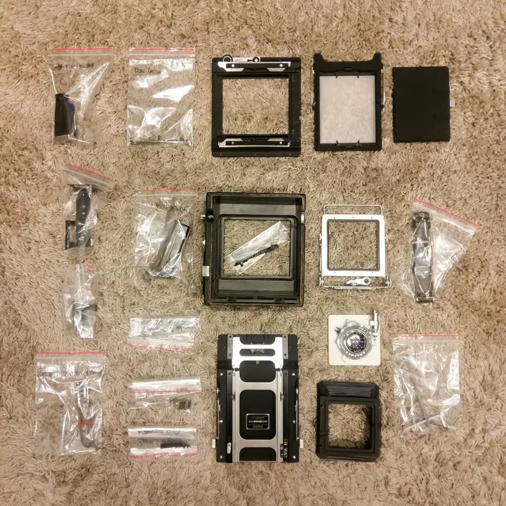
There you go. The smoke has cleared and you now stand alone, surrounded by neatly bagged up and labelled parts. Something a probably a bit like this:

You’ll note that the front standard and bellows have been disassembled. This is entirely optional and only needed if your front standard is in need of heavy cleaning, or if your bellows need repair. It’s up to you if you want to do this yourself.
If you do, the bellows can be removed by unscrewing the lens board locks. Be careful to note the placement of the washers that live here – they will need to be re assembled exactly as you found them.
At this point in your build you should have a deep feeling of anxiety, concern for your sanity and will most likely be questioning why on earth you let me convince you to take on such a fool’s errand.
That’s perfectly normal and you’ll be ok. Trust me.
Feel free to jump on over to the other parts of this series using the links below:
- The AEROgraphic project part 1 – introduction and required materials
- The AEROgraphic project part 2 – disassembly and strip down (this article)
- The AEROgraphic project part 3 – preparing and finishing the body
- The AEROgraphic project part 4 – reassembly
- The AEROgraphic project part 5 – focal plane shutter and rangefinder tuning
- The AEROgraphic project part 6 – conclusion and example images
Thanks for reading, I’d love to hear your thoughts below.
~ EMULSIVE
Share your knowledge, story or project
The transfer of knowledge across the film photography community is the heart of EMULSIVE. You can add your support by contributing your thoughts, work, experiences and ideas to inspire the hundreds of thousands of people who read these pages each month. Check out the submission guide here.
If you like what you’re reading you can also help this passion project by heading over to the EMULSIVE Patreon page and contributing as little as a dollar a month. There’s also print and apparel over at Society 6, currently showcasing over two dozen t-shirt designs and over a dozen unique photographs available for purchase.


2 responses to “Building a naked Aero Ektar Speed Graphic: The AEROgraphic project part 2 – disassembly and strip down”
Thanks a ton for this series. I am not sure I am yet ready to take the plunge and strip the Speed Graphic I have that used to be my father-in-law’s down and have a wood finish but everything else has been hugely helpful as I work to restore it.
One thing I am currently stumped by is releasing the bellows from the rear of the camera. Mine is a regular SG from about 1940-1942. it doesn’t have the clips you show. Any other advice on how to approach this?
Thanks,
Nathan
4.5