I have always wanted a Jobo film processor. For years the idea of having a temperature-controlled water bath and a roller based agitation system sounded like the best way to process my film. But the cost of purchasing a new or even used Jobo it quite high. I just could not justify this kind of expenditure for a hobby.

I am quite handy and decided I could build one quite easily using simple materials and low-cost micro-electronic controllers. I also decided that I would document this process so you could make one too. Most of the construction is quite easy.
As far as the hardware and software, I will make some recommendations and publish the program that I wrote and some alternatives solutions that will make it easy for you to build the electronics portion quite easily.

The total cost of the system is well under $300. I have quite a few electronic controllers, motor drivers and motors laying around, so I could make this for a bit less.
You can still build one for less than $300. Also, I built the core container out of wood, you could build your water tank container using whatever you have at home, like a plastic container or an ice chest.
The build instructions will take this into account and you have the flexibility to customize your design to fit your situation. I am also available to give pointers and make recommendations. I am part of the film community and like to give back to our community.
I’ll be breaking this project up into a series of two articles. This first part deals with the basic construction. Here’s what’s covered:
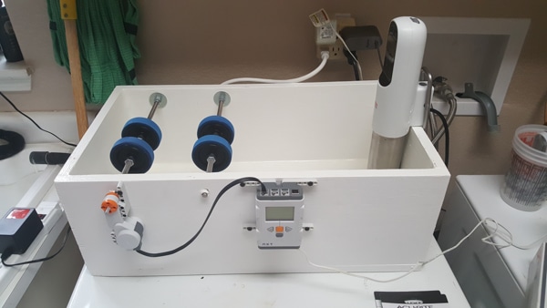
The finished film processor

Pre-requisites
Before we jump in, I’ve listed some basic materials you’ll need before you begin. This part of the project will take approximately 10 hours to complete (on the conservative side). The total project should clock in at 15-20 hours.
Ultimately, the amount of time you spend on this project will be dictated by your level of experience but don’t fret, I’ve kept is so simple that you could put this together with a bit of forethought and planning alone!
Let’s take a look at the basic skills, parts and consumables you’ll need:
Required skills/experience
- Ability to use basic hand tools
- Ability to use hand power tools, circular saw, drill, sander etc.
- Ability to safely mix and apply paint and epoxy products.
- Wear personal safety equipment i.e. safety glasses, gloves, respirator
- Ability to handle basic photography chemicals and their disposal
Required tools and consumables
- Power drill, circular saw, sander.
- Screwdriver, hammer, hacksaw, center punch (or nail used instead of center punch).
- Drill bits (various sizes).
- Tape measure or ruler (Metric or US Standard).
- Paint brushes, nails or screws to assemble water box.
- Paint, wood glue, epoxy.
- 36” length, 3/8” diameter threaded rod
- 16 – 3/8” nuts
- 3/8” larger washers
- 4 – 3/8” threaded brass inserts
- 1 – 1/2” brass hose bibb (water faucet)
- 4 – 2” rubber and plastic caster wheels
- Can of wood putty (I used Bondo wood filler, use what you can get)
- Filler epoxy (used to epoxy the water faucet to the box)
- 1 quart of Paint, if you are building a wood box
- Waterproof clear coat paint ( I used Clear Satin Water-Based Outdoor Spar Urethane)
(I purchased a spray can, you do not need a quart) - Sous-Vide controller, used to control temperature and circulation.
(I purchased my controller from Amazon for $40.00) - 3/16” drill bit, make sure it is sharp
- Center Punch (hardware store)
- Nail with a sharp point, you could use this instead of the center punch
- Center drill, you could use a smaller drill bit instead
- Felt-tipped pen
- Small fine division ruler (1/16 or smaller)
With that out of the way and assuming you’re set with the materials above, let’s get started.
Instructions – Basic Construction
Step 1: The Heated Water Tank
This is the basic shell of your automatic film processor. Everything else will fit on, around, in or through this tank.
I decided to construct a wood box with the dimensions of 12” x 24” This size is more than likely too big for your design, so your design can be smaller. You may also use a plastic container or an old ice chest. Use anything you may have to keep the cost down but make sure it’s watertight

My reason for a wood box was to make sure that the roller assembly would be rigid. You could use wood blocks to brace you plastic container or ice chest as well.
I picked up some 3/4” plywood and cut the pieces to size, 12” x 24”. I glued and nailed the box together. To make sure then box would not leak I applied some waterproof wood filler along the joints of the box. You want to make a nice fillet with the filler so the water box will not leak.
Step 2: Tank roller hardware and drain
The roller hardware is what your Paterson (or other brand) film development tank will rest on. The image below shows the finished construction.
I listed the parts that you need to build the roller assembly and finish the water box above but they’re below the image for quick reference.

List of Hardware
- 36” length, 3/8” diameter threaded rod
- 16 – 3/8” nuts
- 3/8” larger washers
- 4 – 3/8” threaded brass inserts
- 1 – 1/2” Brass hose bibb (water faucet)
- 4 – 2” rubber and plastic caster wheels
- Can of wood putty (I used Bondo wood filler, use what you can get)
- Filled Epoxy (used to epoxy the water faucet to the box)
- 1 quart of Paint, if you are building a wood box
- Waterproof clear coat paint ( I used Clear Satin Water-Based Outdoor Spar Urethane)
(I purchased a spray can, you do not need a quart) - Sous-Vide Controller, used to control temperature and circulation.
( I purchased my controller from Amazon for $40.00)
Step 2.1: Prepare the threaded rod

You will need two pieces of threaded rod. The length of each rod will depend on the width of your water tank. Since my water box is 12 inches wide, I needed two rods that are a bit longer than 12 inches. I cut mine to 15 inches. You will need extra length in order to attach the nuts onto the rods to hold the rods in place.
You also need some of that extra rod length to attach the controller motor to the threaded rod. The motor will drive the rod and turn your film development tank during development.
Use a hack saw, a grinder with a cut off wheel or a metal cutting band saw, whatever you have available.
After you cut the threaded rod, file the ends to remove the burrs. This will allow the nuts to thread onto the rods easily (also you do not want to cut yourself on the sharp metal).
Use a file, or a bench grinder or a belt sander to clean up the rod ends.
Step 2.2: Prepare the caster wheels
If you are located in the USA, the best location to purchase the caster wheels is Harbor Freight Tools. For our friends across the ocean, I am sure any import tool supplier should carry similar caster wheels.

You must remove the wheel from the caster assembly. To do this take your drill and drill out the riveted head of the axle that holds the wheel to the caster base.
Set the caster wheels aside for the time being.
Step 2.3: Drill out the center of the caster wheels
In order for the caster wheels to fit on the threaded rods, drill out the wheel center holes to fit the threaded rod. Use a 3/8” drill bit and hold the caster wheel with a pair of pliers, or place the caster wheel in your hand vice and carefully drill out the center hole.
IMPORTANT: make sure you try to keep the drill centered along the centerline of the wheel.

Step 2.4: Drilling the threaded inserts

We need bushing for the threaded rod to rotate on when it’s mounted inside the water tank. Locate the 4 brass threaded inserts from your parts list, place them into a small hand vice, or hold then with a pair of pliers.
If you purchased 3/8” threaded rod then we will need to dill out the threaded inserts with a 3/8” drill bit.
When drilling try to hold your drill parallel to the centerline of the hole, you want your threaded rod to not bind in the holes in the water box.
Another option is to insert the threaded inserts into the holes in the water box and then drill out the holes in the threaded inserts.
See section “Step 2.6: Drilling the holes for the roller assembly
Step 2.5: Sizing the Roller Assembly
Sizing the roller hardware for the development tank you are going to use. If you want to use different diameter development tanks, You can always drill an extra hole for proper spacing.
Take a look at the below image; I will walk you through the sizing process:

Notice that I placed a bottle of chemicals inside of the box, I want to make sure the water level is high enough to heat the chemicals as well as provide a proper water level for the roller assembly.
The development tank will actually sit below the roller assembly. The water level will hold the development tank up against the rollers. But for sizing purposes, we will place the development tank on top of the roller assembly.
In my laundry room, the sink is to the left of the location I want to place the film processor, so I am going to arrange the roller base on the left side of the water box.
Lay your threaded rods into position. The caster wheels must be placed into a position where the tank diameter is the same. Notice my development tank has a larger diameter near the lid of the tank. I took that into consideration and placed the wheels further into the water box.
You do not want the threaded rods too close to one another or too far apart.

I am using an Arista Development tank so my spacing is set to 5 1/2”. Your fit may be different.
Set your tank on top of the rollers and gently try to roll the tank while lightly holding the threaded rods in place, The threaded rods should turn, not the wheels themselves.
Once you determine the proper width of the threaded rods, you want to determine how high or low the roller base will sit down inside the water tank.
You want a water level high enough to keep your chemical bottles in place and warmed properly, but not too high that the bottles will start to float.
You also want the roller base low enough so that the water level is high enough to hold the tank against the roller wheels.
This process involves some trial and error, but if you take your time you will get it right. You can always re-drill new holes and fill the old holes in with wood or plastic filler.
Once you determine the proper height, and width you want to write these dimensions down.
We will now drill the holes in the water box.
My hole dimensions are the following, First hole 3 1/2” from the left side of the water box.
The center of the hole is 1” from the top of the water box.
The second hole is 5 1/2” from the first hole, Or 9” from the left side of the water box.
Step 2.6: Drilling the holes for the roller assembly
I marked the hole centers as described in the above paragraph. The drilled out threaded inserts are shown in the above image.
Drill the holes. In order to have enough clearance to screw the threaded inserts into the drilled holes we need to use a 1/2” drill bit.
I used a dowel pin-drill guide to drill the holes. You want to keep the holes parallel.
But after I drilled the holes and inserted the threaded inserts. I could easily re-align the threaded inserts by inserted the threaded rod into the threaded insert and slightly bending up or down to re-align the hole locations.
So if you do not have a dowel drilling jig, go ahead and drill the holes, just make sure you drill the holes parallel to the top of the water box.

Once the holes are drilled we can insert the threaded inserts into the drilled holes.
The threaded inserts have a slot cut into one end. This slot is used to screw the threaded insert into the hole.
I used a small wrench as a tool to screw the inserts into the wood.
In fitting my threaded inserts I screwed the inserts in and out several times to check the fit. As a result, when I screwed the inserts in for the final time the brass slots broke off.
If this happens to you, just screw the inserts into the hole using a pair of needle-nose pliers.
Make sure that the threaded inserts are flush to the wood on the inside of the water box. You will be placing washers on the threaded rod up against the wood water box.


Step 2.7: Install the drain faucet
On either end of the water box, near the bottom of the water box, Drill a 7/8” hole for the water faucet.
In the image shown below, I drilled a hole into a test piece of wood, as I had installed my drain off camera.

Once you drill the hole we can epoxy in the faucet. Notice I placed a few washers under the faucet base and handle to slightly raise up the faucet. This is to provide clearance to rotate the valve freely.
In the image shows the type of epoxy I used to seal the faucet to the water box. This epoxy is a two-part filled epoxy. You cut off a section, knead the epoxy to mix part a and part b together.
Place a strip of epoxy around the rear end of the faucet and insert the faucet into the drilled as shown in the above image.

Cut another section of epoxy, mix and lay a fillet of epoxy around the base of the faucet to seal the faucet against the wood.
To make it easier, you may want to wait for the epoxy to cure before laying the fillet around the base of the faucet, so you can remove the washers.
Step 3: Paint or seal the water tank

If you are using wood for your water tank, you must paint it. I used a waterproof stain and sealer I purchased from one of the big box hardware stores.
After the paint is dry, you want to spray the inside of the water box with the Clear Water-Based Outdoor Spar Urethane from the parts list above.
If you decided to use use a plastic container or ice chest, you can skip this section.
Step 4: Install the sous vide controller
Install the Sous-Vide Temperature/circulation controller. This is quite easy. The Sous-Vide controller has a hinged clamp on the rear side. Just clamp the controller on the water box.

End of part 1 – lessons learned
This is the end of part 1 of this build. Part 2 will contain the steps to build the roller base motor and controller, some testing and additional tweaks.
As with any projects, I learned quite a bit during the build and want to share it with you here.
First, build your water box a bit smaller.
A 12” x 24” x 8” tank takes 6.5 gallons of water to fill up to the correct level – a bit more water than I wanted to use. I will more than likely cut the water box down a bit to hold a bit less water.
If you purchase less expensive wheels for your roller assembly, then you will more than likely need to sand the dome shape from the wheels to provide a greater surface to grip the development tank.
When testing I noticed some slipping. If you do not have a lathe, use a drill and a short section of threaded rod and two nuts, to attach the wheels and sand the wheels to have a flat surface.
Check out the images in the gallery below (click to enlarge):


The first image shows the stock wheel. Notice the contact patch of the wheel. only the very domed part of the wheel would have contact with the development tank.
The second is an image of using the drill, the threaded rod and two nuts to sand the wheel to have a flat surface for a better contact patch:
The final image showing the better contact patch after the wheel has been sanded smooth.
If you’d like any clarification on any of the steps or rationale described here, please leave a note in the comments below.
See you in part two.
~ Joe Pitz
Share your knowledge, story or project
The transfer of knowledge across the film photography community is the heart of EMULSIVE. You can add your support by contributing your thoughts, work, experiences and ideas to inspire the hundreds of thousands of people who read these pages each month. Check out the submission guide here.
If you like what you’re reading you can also help this passion project by heading over to the EMULSIVE Patreon page and contributing as little as a dollar a month. There’s also print and apparel over at Society 6, currently showcasing over two dozen t-shirt designs and over a dozen unique photographs available for purchase.


8 responses to “How-to: Build your own JOBO-style semi-automatic film processor: Pt.1”
Instead of cutting your tank down to reduce the volume of water just put something in the tank to displace some of it.
Could i just use the sous vide for warming photo chemicals?
@joe_pitz_photos Pretty awesome. Started one myself but this will make the build even better! Thanks for sharing!
que onda Pablo, vos decis que se puede?
@joe_pitz_photos Lilly, I thought of you when I saw this! :-))
@joe_pitz_photos Cool project and kudos for it being LEGO powered. :p
@joe_pitz_photos Very cool!
This is amazing. I did a similar project once but I failed at some point. Looking forward to part 2!