Welcome to part five – the penultimate part – of the AEROgraphic project. In this article you will finally be finishing your build. Rest easy, as part six is purely to show off some of the photographs I’ve taken with my own. As with the preceding parts of this series, I strongly recommend you visit what’s come before in order to bring yourself up to speed:
- The AEROgraphic project part 1 – introduction and required materials
- The AEROgraphic project part 2 – disassembly and strip down
- The AEROgraphic project part 3 – preparing and finishing the body
- The AEROgraphic project part 4 – reassembly
- The AEROgraphic project part 5 – focal plane shutter and rangefinder tuning (this article)
If you’re all caught up, it’s time to begin fine tuning your camera. Here’s what we’ll be covering in this article:
Your time cost
Step one will require approximately an hour of your time, as you will need to measure your focal plane shutter speeds and potentially tweak your shutter tension until they’re set correctly. Once set, you will not likely need to retune your focal plane shutter for some time.
Steps two and three are relatively simple and can be finished within about 30-45 minutes. The fourth step – rangefinder calibration – will need a good few hours and lots of patience to get right.
The tools and materials you will require are as follows:
- Precision screwdriver set (flat head).
- Needle-nosed pliers.
- Painter’s tape.
- A small pair of scissors.
- A fine-tipped Sharpie and pencil.
- A magnifying glass or loupe.
- An SLR camera or calibrated external rangefinder.
- Optional tools and materials are:
- A shutter speed tester tool (photocell, not sound based).
- A good torch.
- A computer with Audacity installed and a working microphone/headset jack.
You’ll recall I mentioned the shutter speed tester back in part one. This simple tool comes in two parts, a light source and a photocell wired to a 3.5mm microphone jack. You can make one, or purchase one off the shelf for about $20.
There are more expensive versions with integrated LCD panels available and if you have one of these, you won’t need to install Audacity, as the tool will give you a readout directly.
Let’s get started.
Step 1: Focal plane shutter tuning
If you do not plan on using your Speed Graphic’s focal plane shutter you can skip straight to step 2. Assuming you set your focal plane shutter as per the reassembly instructions in part 4, you will most likely be all set to use your shutter at all speeds. That said, with a camera of this age it’s always worth double-checking your shutter speeds for accuracy.
You can do this by sight and sound if you feel up to but I prefer something a little more objective in the form of a photocell, light source and audio recording software (Audacity). The set-up is much simpler than it sounds.
First, remove your Graflock back and mount and set them aside. Remove your shutter mechanism’s cover and set your shutter to its open position (“O”). Make sure that your shutter curtain is positioned as shown in the image below. If it’s not, follow the instructions for rebuilding your shutter in part four.

Next, open the door and install you Aero Ektar and set to the widest aperture. If you are using a different lens, cock the shutter and set it to its preview mode to open the shutter iris.
Place the photocell so that it’s lined up with the center of the shutter at the rear of the camera. You may find it easier to affix the photocell to something you can position near the read of the camera – I use a USB hard drive. However you position the photocell, just make sure that it’s not touching the shutter curtain.
Plug the photocell into the microphone/audio jack on your computer and open Audacity. Press record, then shine a torch through the lens for a second or two. You should see audacity record a blip. Stop the recording. If you do not see a blip, you need to check the photocell is functioning. Try placing the entire setup in a dark room and try again.
Once you have confirmed the photocell is working, cycle your camera’s shutter to the 1000 speed setting, ensuring that the shutter governor switch (marked (C) below), is flipped to the left.

Start a new recording in Audacity and turn on your torch then shine it through the lens. Cycle through your shutter three times – 1000/sec, 250/sec and 50/sec – pausing the recoring when you reach the “T” setting.
Turn your shutter speed selector to 1000 again and this time flip the governer switch (C) to the right. This will enable the Speed Graphic’s slow speed setting and the shutter speed mask mask should now show “500” in its window.
Unpause your recording and once again, shine your torch through the lens before cycling through your shutter three times – 500/sec, 125/sec, 30/sec – stopping again at “T”.
Stop your audacity recording and save it. Your file should give you a reading that looks something like the image below with the fast speeds on the top row and the slow speeds on the bottom row.

You’ll need to analyse each waveform to confirm the length of each shutter pass. You do this by zooming right in and reading between the peaks on each waveform as per the highlighted area in the example below. Make a note of the time in milliseconds between each peak and convert them to tenths/thousandths of a second. You may find it easier to use this spreadsheet to help you keep track:
Graflex Speed Graphic shutter speed calibration record
If you find that your shutter speeds are off enough to be a concern (anything more than half a full stop), you should wind (or unwind) your shutter tension screw appropriately as per the instructions below.
Hold down the shutter spring washer (A) with your finger or thumb while you slowly unscrew the retaining bolt (B) about one full turn. Ensure (C) is positioned to the right.
As you unscrew the retaining bolt you will feel that washer wanting to move against your finger or thumb – don’t let it.
If for some reason the shutter tension is released, you will need to reset your shutter as per these instructions.
Once the washer is free of the retaining bolt, slot a flat head screwdriver into the shutter roller bar and:
- Unwind clockwise half a turn if your shutter is too fast.
- Wind counter clockwise half a turn if your shutter is too slow.
Tighten the retaining bolt (B) and then run through your shutter speed test above again. Repeat this process until you are happy with your shutter speeds, winding/unwinding a quarter of a full rotation if you want to REALLY nail down your speeds.
Once you are satisfied with your speeds, move to step 2.
Step 2: Setting infinity focus
Now for something a little easier! We are going to determine the correct position of the front standard to ensure that your lens is able to achieve an infinity focus without you needing to confirm using your ground glass every single time.
Grab your camera, the Aero Ektar (with lens mount), a suitable tripod and the required tools/materials above and head somewhere where can get a clear and uninterrupted line of sight of a building or other feature at least 1 mile / 1.5 kilometres away.
It will help if the building or object you will use as your target is approximately parallel to the camera and that the camera is angled up less than 15 degrees.
Your camera should have come with two infinity stops mounted on the focus rails. When flipped down, they permit you to move the front standard freely along the focus rails but when flipped up, they stop all movement past the stops.
Each lens you will use with your Speed Graphic should have a pair of correctly set infinity stops but if you’re like me and have more than a few you cycle through, you may simply want to set one or two pairs for the lenses you use most.


To set infinity focus for the Aero Ektar, mount the camera to your tripod, open the door and mount the lens to the front standard.
Make sure the lens aperture is set to f/2.5 and that there is no filter or lens cap installed. Next, cycle your shutter to the “O” setting (open) and open the door to the ground glass at the rear of the camera.
If the focus screen remains dark, make sure your shutter is correctly set to “O” and that the shutter curtain is positioned as per the instructions in part 4.
Unscrew your infinity stops by half a turn on each screw then slide them to the front of the focus rails and tighten one screw on each.
Unlock your front standard and pull it out so that the rear of the lens is approximately 18cm from the ground glass.
Note: large format lenses typically need to be roughly the same distance from the ground glass/film plane as their focal length in order to achieve focus to infinity. It doesn’t really matter which lens you use for this rule to apply. Although there are some lens designs which permit a closer infinity placement I’m not going to talk about those here.
With that distant object in view, use the image on your glass to check focus. You will need to move the front standard a closer to or away from the ground glass until you have you have an image that’s in perfect focus.
Use your magnifying glass or loupe to confirm your focus is accurate and if necessary, slowly rack your focus wheels back and forth to confirm. Lock your front standard, taking care not to move it back or forth along the focus rails.
Unscrew and slide your loosened infinity stops (in their raised position) back to the front standard and lightly push them against it. Tighten the outermost screw on each, ensuring that the stops are secured exactly parallel to one another.
Check your ground glass image and if it’s still totally crisp, unlock your front standard and slide it back into the body. Screw the rearmost infinity stop screws down.
That’s it.
You can repeat this process with any lens you have, and add as many infinity stop pairs as you have lenses to your focus rail.
Step 3: creating a custom focus scale
In this step, we’re going to create a custom focus scale for your Aero Ektar lens. To do this, you will need to either make a new scale using your existing scale as a guide, or use the painter’s tape to cover the existing plate.
That’s what I did and I’m going to assume you’ll be doing the latter.
We’re first going to find the the closest and furthest focus distances that are possible to measure using the scale. Once these have been determined, we’ll be setting a few intermediate distances.
The marks you will set on your scale will allow you to achieve ballpark focus.
The Aero Ektar focused on an object 4 feet away at f/2.5 will give you a depth of field of somewhere in the region of 5 centimetres and as long as your marks are within this level of tolerance, images taken should be acceptably in focus. That said, remember that this isn’t a critical focus tool!

The scale I made for this project covers 4-15 feet with intermediate distances of 5, 6 and 8 feet. I chose these distances as they’re what I will work best for my particular use case but you can set yours however you choose.
Unscrew your existing focus scale and remove it from the focus rail guide (the black bar that secures the left of the focus rail into place. Cover the scale with a strip of painter’s tape and cut off the excess before remounting it.
Flip up your infinity stops, then unlock and pull out the front standard until it stops. With the front standard up hard against the infinity stops, lock it in place.
You may need to pick up and move your camera around depending on how “busy” your environment with appropriate subjects parallel to your camera at a 4-15ft distance.
Setting close focus ~4 feet
Use your SLR to focus on an object 4 feet away, making sure that the film plane of the camera is parallel to that of your Speed Graphic.
The reason we’re using an SLR camera is that the lens barrel markings at the distances we’re working at will be close, if not identical to those you will be making for your AREOgraphic. Whilst you may use a rangefinder (standalone or camera) to check distances, these may not be accurate depending on the camera’s age.
By far and away the most accurate solution will be to use a laser rangefinder (just in case you have one lying around).
Having identified an object 4 feet from the Speed Graphic with your camera, use your ground glass to focus on the same object. If the focus arrow plate (mounted on the focus rail) doesn’t match up to the far end of the newly covered focus scale, you can loosen its screws and slide it forward until the arrow is pointed to somewhere you can reasonably mark a fine line and note the distance.
Confirm that the image on your ground glass is sharp and use your pencil to make a mark where the arrow is.
Setting far focus ~ 15 feet
Repeat the process above for an object 15 feet away. The focus arrow plate should be a few milimeters from the rear of the focus scale.
Setting intermediate focus marks ~4-15 feet
What you set for your intermediate distances is totally up to you. As you’ll see from the image above, I set 5, 6 and 8 feet. Follow the steps above to focus on and mark a succession of distances, confirming focus on your ground glass for each and making an appropriate mark on the focus scale.
When you are done, double check each of your distances and adjust your focus guide as necessary.
Step 4: Calibrating your Kalart rangefinder
Inspiration for the instructions you see here came from the Kalart Rangefinder manual over at Graflex.org and Jo Lommen’s excellent Speed Graphic / Aero Ektar resource. I would highly recommend you head over to both and read through the excellent materials provided.
Before you begin this step, make sure you have at least 2-3 hours set aside. Your initial rangefinder calibration can be deceptively quick but you will need to check and recheck all your focus points over and over again before you are finished.
We will be setting the rangefinder for infinity, 25/15 feet and 8/4 feet. Setting your rangefinder requires a lot of jumping back and forth, checking, rechecking and tweaking each distance.
The side mounted rangefinder doesn’t technically stretch to use with the Aero Ektar lens but its close enough to work reliably down to about 6 feet from infinity. You may decide that it’s easier to simply set infinity and 25/15 feet. See how you go, it’s totally up to you.
To save yourself more time and hassle, set yourself up in a room near a window, with the camera pointed to a distant object. As you’ll be removing the rangefinder’s cover, being in a darkened room will make it easier to view the rangefinder splitter. The rest of your calibration will mostly be focused inside, where you can better control your focus points without moving the camera around.
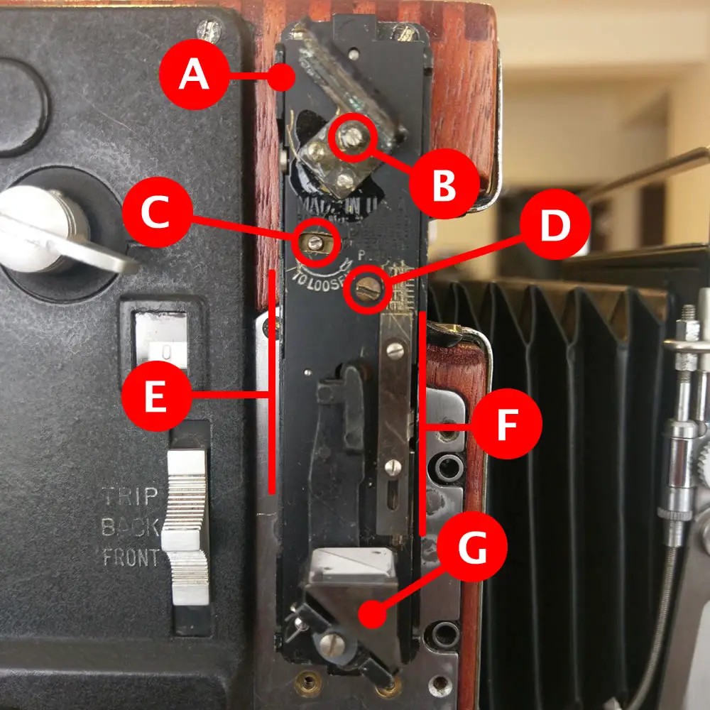
Remove your rangefinder’s cover and use the examples below to familiaraise yourself with the rangefinder mechanism. It may look complicated but once you’ve labeled everything it’ll all become very clear.

(A) = Rangefinder patch/splitter
(B) = Lateral shift adjustment
(C) = Rear focus adjusting screw
(D) = Rangefinder base mounting screw
(E) = Rear scale slide
(F) = Front scale slide
(G) = Prism
Reset your rangefinder
Before you do this, we need to reset the rangefinder mechanism. To do this, begin by putting the camera onto its left side and then remove screw (D) in the image above. With the screw free, carefully lift the mechanism straight up without touching the glass splitter or prism and set it aside.
You should see this small brass cam underneath it.

With your camera on a tripod and no lens installed, lock the front standard at the halfway point on the focus rails and rack them out as far as they’ll go. Use the focus tension bar on the front right of the bed to lock your focus rails into place.
You should see a small assembly near the rear of the focus rails. This is an eccentric screw and is used to fine-tune your rangefinder’s infinity setting (see the image below). Use a coin to slowly turn the screw so that it is set to a vertical position.

Remember your rangefinder arm mounted inside the top left of the camera body? We need to reset it’s position, too.
When secured to the pin on the rangefinder base, the arm is spring loaded and will move the cam in the first image above as the eccentric screw pushes against it. See the short video below for an example of how this works.
We need to reset the cam to ensure that we have an optimal starting position for the rangefinder arm and an appropriate “base” to set infinity from.
The rangefinder arm will normally not move past the bed hinge support inside of the body. You will need to locate the arm and jiggle it a bit so that it can move forward, free of the hinge. To do this, it will be easier if you unscrew the small bolt that secures it to the rangefinder pin by about half a turn.
Once the arm is free and as far forwards as it can go, loop a rubber band onto the bottom of it and secure the other end onto the front standard as per the image below.

When you are happy that the band is secure, push the arm back to it’s normal position, so that it’s behind the bed support hinge once again. Rack the rails back all the way into the body and use your torch to confirm that it’s still in contact with the eccentric screw.
The brass cam on the rangefinder’s mounting plate will likely have reset by now and will be pushed up against the right hand side of the plate.
With the rangefinder arm’s locking screw still loose, move the cam with your finger so that it is 9-10mm from the left of the plate. Holding it in place, tighten the rangefinder arm’s retaining bolt.
Rack out the focus rail and remove the rubber band. If you rack the focus rail in an out, you should see the cam moving accordingly (per the video above). If so, rack the rails back into the body. If not, repeat the process.
Setting your rangefinder to infinity
Here’s the image of the rangefinder mechanism again:
Replace the mechanism while making sure that you have pulled the rear adjusting screw all the way to the left (C). Once the mechanism securely in place, screw in (C).
If you rack out the focus rails, you should be able to see the prism (G) moving. Give the circular windows of the rangefinder cover a clean using a q-tip and some alcohol/acetone/water and carefully clean the prism. I would advise you not to clean the splitter (A), unless you are absolutely confident what you are doing. The silver coating will likely have become brittle and could be very easily be removed rendering the rangefinder useless.
With everything set and the rangefinder cover secured in place, it’s time to get infinity focus.
With your focus rails racked all the way back, the Aero Ektar mounted and the front standard pulled to the infinity stops, look through the rangefinder window with the camera pointed to the distant object and asses your rangefinder reading.
If your rangefinder shows some lateral (left/right) shift, adjust screw (B) by tenths of a turn to bring it into alignment. You may find it useful to add a dab of PVC glue, or a tiny ball of Blu-Tack to the screw head to ensure that it won’t move again.
If your infinity focus is misaligned in the up or down position, you will need to first identify how the moving image is misaligned.
If the image is ABOVE center, rack out the focus until you can see the eccentric screw and give it a small turn clockwise equivalent to about 30 minutes on a clock. If the image is BELOW center, turn the same screw backwards by the same amount. Rack your focus rails back into the body, check infinity and adjust again as required.
Fine tuning your rangefinder for 25, 15 and 8 feet
With the focus rails, lens and rangefinder still set to infinity, we need to make a small adjustment to the rear and front focus before beginning our fine tuning.
Remove the rangefinder cover and familiarise yourself once more with the rangefinder mechanism:
We need to set our rear and front scales (E) and (F) to #17 and #6 respectively. You will need to loosen a screw or two before you begin. Depending on the age of your rangefinder, you may find that the front scale (F) doesn’t have numbers marked. If this is the case, set (F) to the sixth mark from the top.
Tighten the screws on each scale and double check that the rangefinder is still set to infinity. If not, adjust your eccentric screw as per the previous step.
If your infinity setting is good, use your ground glass to focus on an object in the room that is exactly 25 feet away and parallel to the rangefinder. Use your SLR to confirm.
Once you have confirmed focus, check your rangefinder. If the images do not coincide, loosen the screw on (E) and slide the scale up by one mark if your moving image is BELOW the fixed image. If the rangefinder’s movable image is ABOVE the fixed image, move the slider up.
Once set to your satisfaction, rack your focus rails back in and focus on the far away object outside of your window once more.
If your infinity setting hasn’t moved, great! You can repeat the above step for 15 feet, check infinity and then set 10 feet…and check infinity.
Unluckily for you, your infinity setting will most likely have changed and you will need to go back to “Setting your rangefinder to infinity” above and adjust the eccentric screw to suit.
You will need to jump from infinity to 25 feet, back to infinity, to 15 feet, back to infinity, etc., until your rangefinder setting is accurate, or acceptably accurate for your requirements.
On my AEROgraphic, my rangefinder is accurate to all three distances I decided to measure: 25, 15 and 8 feet. It’ll take some time but you will get there.
End of part five
That’s the build complete. Really, that’s it. Once you have finished the above step, you will have a fully functioning AEROgraphic and will be able to focus with your ground glass, rangefinder and focus scale.
Of course, you can also use the viewfinder frame (not discussed here!) but where’s the fun in that? Anyway, that particular focus aid is more for framing and less for focus 😉
There’s not much left for me to say for this final part of your build apart from congratulations. The focal plane shutter and rangefinder calibrations you completed above will have likely worn you down but I hope you’ll agree they were worth it.
You now have an (almost) one of a kind set-up, perfect for street photography – regardless of if you opted for a 6×12 film back like me. All that remains is to hit the gym and make sure you can lug around the 5-6kg heft of your finished AEROgraphic!
You can use the links below to jump to any part of the AEROgraphic build:
- The AEROgraphic project part 1 – introduction and required materials
- The AEROgraphic project part 2 – disassembly and strip down
- The AEROgraphic project part 3 – preparing and finishing the body
- The AEROgraphic project part 4 – reassembly
- The AEROgraphic project part 5 – focal plane shutter and rangefinder tuning (this article)
- The AEROgraphic project part 6 – conclusion and example images
Keep shooting, folks!
~ EMULSIVE
Share your knowledge, story or project
The transfer of knowledge across the film photography community is the heart of EMULSIVE. You can add your support by contributing your thoughts, work, experiences and ideas to inspire the hundreds of thousands of people who read these pages each month. Check out the submission guide here.
If you like what you’re reading you can also help this passion project by heading over to the EMULSIVE Patreon page and contributing as little as a dollar a month. There’s also print and apparel over at Society 6, currently showcasing over two dozen t-shirt designs and over a dozen unique photographs available for purchase.


2 responses to “Building a naked Aero Ektar Speed Graphic: The AEROgraphic project part 5: Focal plane shutter tuning and rangefinder”
I’m wondering if you can help me determine if I have the correct model 4 x 5. I have the Aero Ektar lens and want to pair them up. I found the serial number: 842016
Do you have a resource where I can determine if my speed graphic is within the age group that is suitable for this purpose?
Hello there.
I am so appreciative of your article on refurbishing Graflex Speed Graphic cameras. I have a Pacemaker Speed Graphic and have a Pentac 2.9 lens I am attempting to mount and calibrate. Specifically, I am following your instructions regarding focus, however, I am finding that I am having to rack the lens out right out past the end to even get it set at four feet. Is this normal? I can’t reset the stops out there because I can’t put them far enough out… anyway, a little frustrating. Any suggestions? Thanks.