I’d been working on this project in one form or another for about 6 months, trying various methods to return the old selenium light meter on my Rolleiflex 2.8F to a functional and usable state. Without giving it all away, this article/informal guide covers the end result of replacing the camera’s original light meter cell with a modern digital counterpart in the form of an Arduino microcontroller — just the cell and the light reading aspect, the way you read the meter and set the film speed do not change!
As you can see, the finished version doesn’t change the look of the camera much — if at all, depending on how close you’re looking!

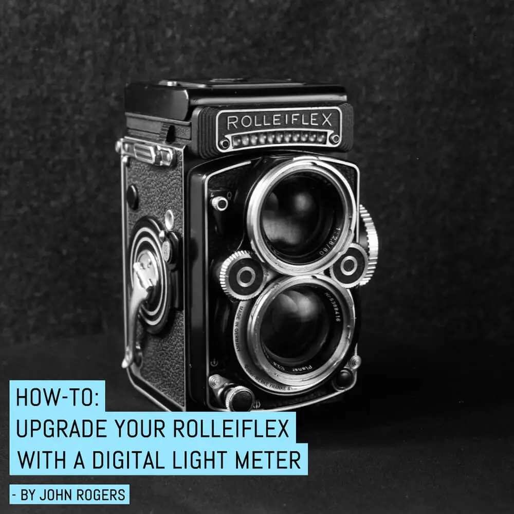
The story starts off with a Rolleiflex 2.8F, which I was sold for a song by a friend. And as with many cameras of its vintage, the selenium cell used to power the batteryless light meter was beyond its expiration date. While using the camera I became quite familiar with using a handheld light meter, even though there was one right there on the camera.
A while back, resolved that the meter would never be useful again, I even bought one of those fancy 3rd party carbon fiber meter plugs to replace the bulky needle assembly that stuck out of the focus knob. That old galvanometer sat in my parts bin calling to me, though. “I’m just a simple needle, I can move depending on the current you give me, certainly there must be some way I can be of some use?”
It got to the point where I couldn’t take it and so, I set off on finding a solution.

Initially, I tried using a modern solar cell to replace the selenium strip that was in there. In summary: no good. I even tried two kinds of solar cells, the monocrystalline type (it favored outdoor light disproportionately) and amorphous (didn’t match the output curve of the meter) so I was forced to try something crazy I’d seen: a CdS cell and Arduino microcontroller.
In 2017, a fellow by the name of Guido Hoss had posted to his blog a project showing how to drive the galvanometer by using an Arduino microcontroller reading inputs from a CdS cell (the project is described on his blog in detail here). In many ways, this was EXACTLY what I wanted to do, save for a few changes due to preference — or laziness — I chose.
Where Mr. Hoss completely replaced the selenium bubble-lens strip, I wanted to keep that in place, because those lenses give the light meter a similar field of view to the actual lenses below. So, I removed only the selenium cell, and epoxied in the bubble lenses and the black housing. I wanted to use as much of the camera’s existing infrastructure as possible, so I reused the selenium cell’s contacts to aid in disassembly should anything go wrong.

I used the “Adafruit ALS-PT19 Analog Light Sensor Breakout” for $2.50 as the light sensor (above). It works very similarly to a CdS cell, except much more linearly. It’s also silicon-based, so I don’t think it’s going bad any time soon. You feed it your input voltage (3.3v in my case) and it outputs a portion of that depending on how much light it sees. Plus, it’s based on an ambient light sensor with a spectral sensitivity very closely resembling that of our eyes, so no worries with it being fooled by outdoor vs. indoor light.
The front plate of the rolleiflex has three screws in it, but if you omit the center one, you have a perfect, albeit tiny channel to run wires to the inside of the mirror box.

Above you can see the wires from the galvanometer (on the right) and the wires to the sensor (left) all converging on the central screw hole. The black wire is the output from the sensor.
Guido used a 3v battery much like I did, but I wasn’t a fan of CR1/3N batteries, so I opted for a CR2032 (the king of batteries!). The smallest Arduino board I could easily source was the exact one he used, an Arduino Pro Mini 3.3v/8mhz. I did have to modify both the CR2032 holder and the actual arduino boards to make them fit.

I removed the reset button from the Arduino, and trimmed a little of the board of the 2032 holder to make it fit a little nicer. I also removed the constant “power on” LED on the board of the Arduino.
Fitting them was fairly straightforward, I used double-sided mounting tape to fit everything, I also had to add a 3.3v step up regulator (much like Guido did) to keep the voltage going to the light sensor consistent through the battery’s discharge cycle.


It took a great deal of pounding my head on my desk and making inquiries with smarter friends the inner workings of Guido’s code. I do very little coding myself, but from what I can tell: the guy’s a coder through and through.
Simply put: the code takes readings from the sensor and gives them a corresponding EV, then gives a series of voltages to output at those EVs and tells the computer to average the in-betweens. It also blinks and LED when it’s too dark or too light, and you can have it output the readings of the sensor for calibration and debugging to a connected computer.
Because I used silicon instead of CdS, my readings were much different than his, and my galvanometer was also tuned differently, but I was able to use my light meter, find an EV, check the sensor, and change the code correspondingly. It took a little trial-and-error, but in the end I got it calibrated and working!

My favorite part of this mod is that it’s a total sleeper – you can’t see it clearly from the outside, though you can see the little silicon square in the middle of the bubbles. And, as I mentioned up top, the way you use the meter does not change in the slightest.
It’s also almost invisible from the ground glass, too. A small shadow on the right is the only thing there to remind you it isn’t stock.

Things I might do differently were I to do it again: actually gluing the boards down to the camera. It would be totally invisible if I could just save about two-strips-of-mounting-tape’s width, but I can’t bring myself to do that. Also, in its current state, the only way to power on and off the device is to reach in and flick the switch that lives on the battery’s breakout board, kind of a hassle. Guido used a reed switch mounted inside the camera, and a magnet in the lid, and while I have both, I have NO CLUE where he could have fitted a magnet strong enough in that origami lid!
As far as photographs made with the camera go…well, they speak for themselves, I think.


All things considered, I find this to be a game-changing mod – the holy grail for me. A built-in light meter I can trust, in a camera I absolutely adore shooting.
~ John
Share your knowledge, story or project
The transfer of knowledge across the film photography community is the heart of EMULSIVE. You can add your support by contributing your thoughts, work, experiences and ideas to inspire the hundreds of thousands of people who read these pages each month. Check out the submission guide here.
If you like what you’re reading you can also help this passion project by heading over to the EMULSIVE Patreon page and contributing as little as a dollar a month. There’s also print and apparel over at Society 6, currently showcasing over two dozen t-shirt designs and over a dozen unique photographs available for purchase.


3 responses to “How-to: Upgrade your Rolleiflex with a digital light meter”
Love people who tinker! Well done and shoot to your heart’s content!
Like your modification. If you got a custom PCB designed so all the components are on one small board you could possibly get a lot of interest.
Regards,
Iain.
I would have just slipped that light meter you used to calibrate the new one, into my pocket, picked up the camera and gone out to take photographs. But that’s just me, lazy, and inclined to spend as little time as possible on things not photography.
dk